
Stepper Controller Motor Driver Module Board
L298N Dual H Bridge DC
Volume Pricing
Introduction
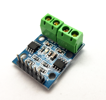
This Dual H-Bridge Motor Driver Shield, which based on H-bridge driver Chip L298N Motor Driver Integrated Circuit, is a usefull module for controlling of robotics and mechanics. It can drive two brushed DC motors or one 4-wire two-phase stepper motor. It is a high voltage, high current dual full-bridge driver designed to accept standard TTL logic levels and drive inductive loads such as relays, solenoids, DC and stepping motors.Both motors can be driven simultaneously while set to a different speed and direction. All driver lines are diode protected from back EMF.
Features
Light weight, small dimension
Super driver capacity
FWD protection
Heavy load Heat sink
Power selection switch
4 pull up resistor switch
2 DC motor/ 4 coil dual phrase stepper motor output
Motor direction indication LED
5V power indication LED
4 standard mouting holes
Specifications
Driver: L298N
Driver power supply: +6V~+35V
Driver peak current: 2A
Logic power output Vss: +5~+7V (internal supply +5V)
Logic current: 0~36mA
Controlling level: Low -0.3V~1.5V, high: 2.3V~Vss
Enable signal level: Low -0.3V~1.5V, high: 2.3V~Vss
Max drive power: 25W (Temperature 75 ???)
Working temperature: -25???~+130???
Dimension: 60mm*54mm
Driver weight: ~48g
Application Ideas
drive brushed DC motors
drive 4-wire two-phase stepper motor
Cautions
Ensure that the positive and negative pole connected to the VMS and GND
Input voltage not exceeding 35V
| Port name | Direction | Description | Usage |
| VMS GND | / | connect to external power supply(6V~35V) | ENA(ENB) connected to H state will enable MOTORA(MOTORB) IN1(IN3) connected to 5V and IN2(IN4) to GND MOTORA(MOTORB) will move clockwise IN1(IN3) connected to GND and IN2(IN4) to 5V MOTORA(MOTORB) will move Anti-clockwise if you want to control speed you can connect the ENA(ENB) to PWM. |
| ENA | Input | TTL Compatible Enable Input:the L state disables the bridge A | |
| IN1 | Input | TTL Compatible Inputs of the Bridge A | |
| IN2 | Input | TTL Compatible Inputs of the Bridge A | |
| ENB | Input | TTL Compatible Enable Input:the L state disables the bridge B | |
| IN3 | Input | TTL Compatible Inputs of the Bridge B | |
| IN4 | Input | TTL Compatible Inputs of the Bridge B | |
| M)TORA | Output | Output of the Bridge A | |
| MOTORB | Output | Output of the Bridge B | |
| CSA(CSB) | / | use for testing electric current of Bridge A(Bridge B) | |
| UR1 UR2 UR3 UR4 | / | pull-up resistor | |
| 5V +5V | / | 5V output | |
| 5V Chip Enable Jumper | / | if connected,5V chip will work. |
Reviews
No reviews yet
Be the first to review this product.
Customers Also Viewed

Stepper Controller Motor Driver Module Board
$15.50